For those of us wanting to view similar information from medium and heavy duty vehicles, such as our motor homes, there are no similar inexpensive solutions. Most commercial software/interface packages cost a thousand dollars or more. A more reasonable priced package is available from Silverleaf, but it still costs several hundred dollars.
However, for less than $50 you can build an interface module to transmit engine, transmission, and other data to any Bluetooth device such as a tablet or PC. While you can read the raw transmitted data using any free terminal emulator program, a simple Android Java app can reformat the raw data into normal values and display it nicely on a tablet.
Here is a photo of the display from this project on my Nexus 7 tablet.

Update - 24-Aug-2014: I just completed a PC version of the app that includes more data. Here is a screen shot with just the ignition on.
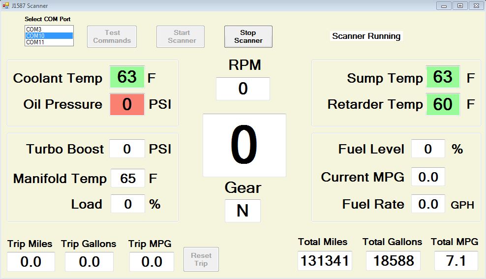
The PC app is written in Visual Basic using the free Visual Studio 2013 IDE. As this is a "work in progress", I have not included any of the project files. Maybe someday.
What follows is a detailed description of how to build the J1587 Bluetooth interface and program the Java app.
The scope of this article is limited to a J1708/J1587 data link interface (hereafter referred to as J1587). There are two data link technologies used in medium and heavy vehicles - J1587 and J1939. J1587 is the older technology. My 2003 coach uses J1587. I do not know the date when coaches may have changed to J1939. J1939 coaches are easier to deal with as you do not have to build an interface. Already built ones are available for $50 or so. It would be a simple task to modify the Java code here for use with J1939.
A detailed reference for J1587 can be downloaded from here: J1587 Reference Document. You will need this as it provides all the MID's and PID's values, and describes how to interpret the data bytes.
Interface
The J1587 bus technology uses RS-485 transceivers to communicate over a twisted pair of wires. The bus can be connected to a computer with a few resistors, capacitors and an RS-485 to TTL converter chip such as the DS485. While such a basic interface is simple and cheap to build, it requires writing a significant amount of code to interpret the data stream into J1587 messages.
A much simpler solution is to connect an ELM325 J1587 interpreter chip to the output of the DS485. The ELM325 takes care of all the formatting for both incoming and outgoing messages. You "talk" to the ELM using "AT" commands similar to those used to communicate with modems. Based on your command, the ELM properly formats a J1587 message and places it on to the bus, receives the J1587 response, reformats it, and sends it to your computer. You can easily monitor the bus to view all the traffic, or you can request specific parameters from any device connected to the J1587 bus. The ELM signal output is normal TTL so you can connect to it using USB, RS232, or a Bluetooth module.
The ELM325 only costs about $15. You purchase the ELM325 directly from ELM Electronics. The datasheet for the ELM325 can be downloaded here: ELM325 Datasheet.pdf
In addition to describing the chip and its programming in detail, the datasheet provides example circuit schematics for USB and RS232 computer connections. I modified the circuit to use a Bluetooth module for the computer connection. Here is the modified schematic:

The changes I made are:
- used a single chip DC-DC voltage regulator to convert from 12v to 5v - 7805.
- used 22pf capacitors instead of 27pf capacitors to load the crystal.
- did not connect the 4 LED's. They serve no useful purpose other than a debugging aid.
- used an HC-06 Bluetooth module for the computer connection.
I first breadboarded the circuit for initial testing.

The only trickly part of constructing the circuit was getting the HC-06 configured to the proper Baud rate. The HC-06 comes set to a default of 9600 Baud, while the ELM325 only communicates at 57600 Baud. Changing the HC-06 Baud rate is simple if you have the necessary tool. I used a USB to TTL interface cable I bought from here: USB to TTL Adapter .
Using a simple console emulator program, such as Termite, and the USB to TTL cable connected to the HC-06, you issue the command "AT+BAUD7". The HC-06 responds with "OK" to indicate the Baud rate was changed successfully.
Two requirements must be met - the command must be sent as all caps, and the HC-06 must not be paired with any device (this was the tricky part that took me while to figure out). You cannot program the HC-06 through the Bluetooth connection. HC-06 instructions can be found here: HC-Serial-Bluetooth-Products.pdf
When you connect the HC-06 to the rest of the circuit, make sure you connect it to the 5v supply not the 12v battery supply. While the HC-06 has an on-board voltage regulator, it is limited to a maximum of 6 volts. I found out the hard way that 12v is too much and will destroy the on-board regulator.
There are many sources for the HC-06. Here is the one I used: HC-06 Bluetooth Module from eBay. This is from a US supplier, so it comes in a week or less. If you are not in a rush, you can order the same item from a China source for dollar or so cheaper. Here is a photo.

Here is what the final circuit looks like:

After I took this photo I added an on-off switch and an LED pilot light.
Connecting to the J1587 Bus
On my coach (and every coach, I guess) there is a 9-pin Deutsch diagnostic connector below the dash next to the driver's left knee.
Typically the pin-outs are:

Note that I said "typically". Coach manufacturers are an independent lot, so check your coach's documentation. J1708+ is J1587-High, and J1708- is J1587-Lo. CAN-H and CAN-L are J1939. On mine, A is battery ground and B is +12v.
You can buy a mating Deutsch connector on eBay and other places. You only need to connect four wires - +12v, Battery Ground, J1587-High, and J1587-Lo.
An alternative is to splice a much cheaper connector (you may even have one in your junk box) directly to the four wires. I used a 9-pin sub-D computer connector and spliced it onto the wires using normal wire splices like you use for trailer wiring.
Displaying Data
For initial testing I used the terminal emulator program Termite. It was useful to view what information was being sent on the bus and to see how the responses were formatted from the ELM325. Interesting and informative, but not what I wanted as a final data display.
My goal was to have a simple display of a few important parameters. I settled on the following six:
- Engine Oil Pressure
- Engine Coolant Temperature
- RPM
- Transmission Retarder Oil Temperature
- Transmission Sump Oil Temperature
- Transmission Current Gear
The four source files are available here: https://app.box.com/s/izs8ld59sfygp1tuldla
I've tried to add enough comments to make the code understandable. But if you have questions, please leave them in the comments section below.
Here are a couple of points of clarification:
1. You need to input the MAC address of your particular Bluetooth device at about line 30 in the java code.
static final String address = "00:14:04:01:28:63"; // replace this MAC with yours
2. You have to pair the two devices before running the app. The code makes the connection for data transfer, but does not do the pairing.